Like all pre-war cars, before we talk about driving, we must first look at how to start the engine! Whereas with a modern car the starting procedure is simply a matter of pressing a ‘START’ button, that of a pre-war car requires a proper procedure where actions must be carried out in a precise chronological order, worthy of a mechanical choreography!
FIRST THREE CHECKS
The first three checks are going to be extremely simple, as we’ll be checking that there is enough engine oil, engine coolant and fuel.
Engine oil
The engine oil level is checked and topped up on the left-hand side of the engine bay.
I use Catrol GP50 monograde oil. Unlike the multigrade oils developed later, monograde oil is manufactured without detergent additives: this prevents residues formed in the sump and on the pistons from being dissolved and dispersed into the oil circuit.
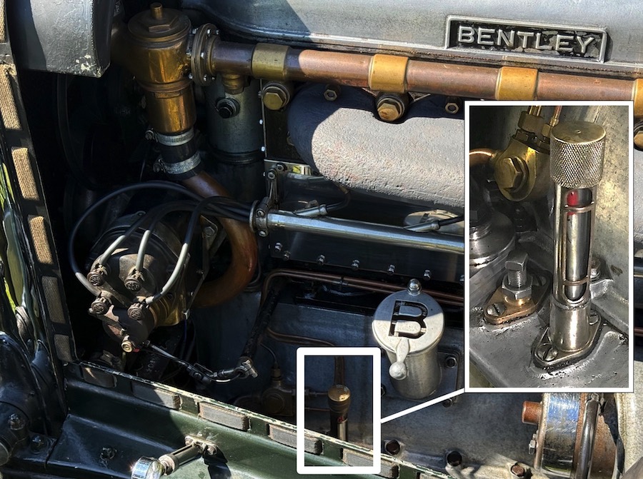
The level is checked via a cylindrical glass tube fitted to a chrome reservoir which has two markings (a high level and a low level). The oil level is observed via a red indicator (resembling that of old mercury thermometers) mounted on a rod-and-float system.
When the red tip of the float needle is in line with the upper line on the casting, the 2.5 imperial gallon (“British imperial gallon”, not to be confused with the US gallon) oil reservoir, equivalent to 11.5 litres, is full. If the red tip is aligned with the lower mark, 1.5 imperial gallons of engine oil, or just under 7 litres, must be added. Oil is topped up via the oil filler cap marked with a stylised “B”.
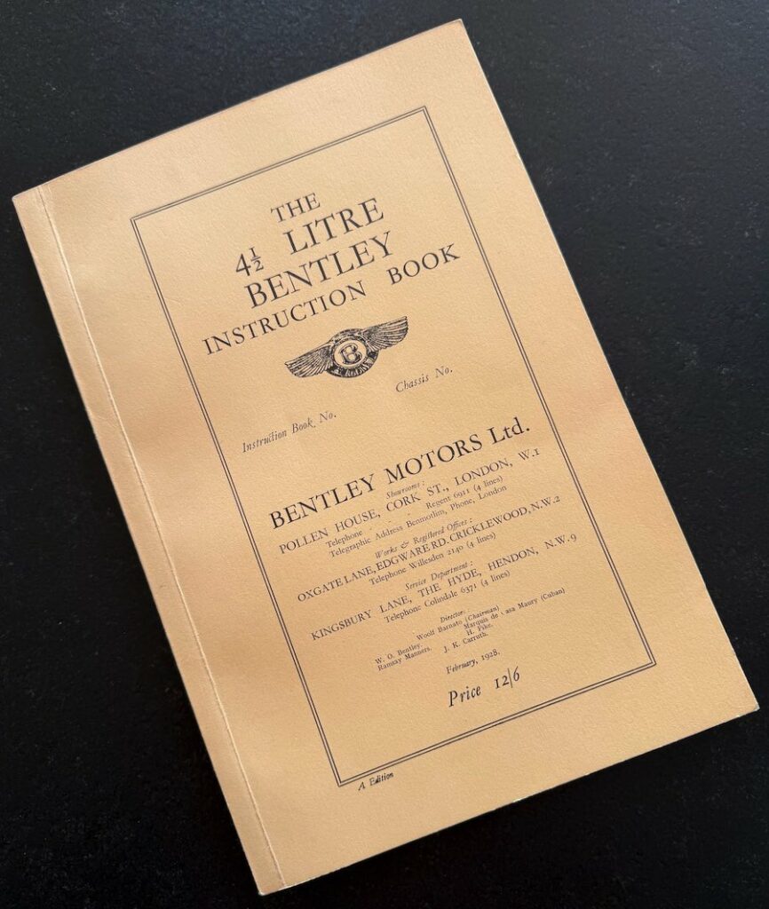
All 4½-litre engines behave differently depending on their specific characteristics, but in the original document provided to new owners by Bentley Motors in 1928 (“The 4½-litre Bentley Instruction Book”), it is stated that oil consumption of around “1,000 miles per (imperial) gallon of oil” should be expected (i.e. 4.5 litres of oil per 1,600 km or 2.8 litres of oil per 1,000 km).
Engine coolant
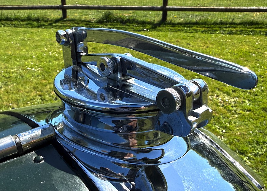
Unsurprisingly, we unscrew the radiator cap and check that the coolant level is about 2 to 3 inches (5 cm) below the lip of the filler. The system holds just over 5.5 imperial gallons (almost 26 litres!).
Fuel level
There is no fuel gauge on this vehicle. This comes as no surprise, as it has never been fitted with one!
Before setting off, I dip a graduated wooden dipstick into the tank, which gives me a good “idea” of how much fuel is actually available. To avoid any nasty surprises and risky experiments, I use only SP98-E5 (also known as “Super unleaded” outside France). The designation “E5” means that the fuel contains up to 5% ethanol.
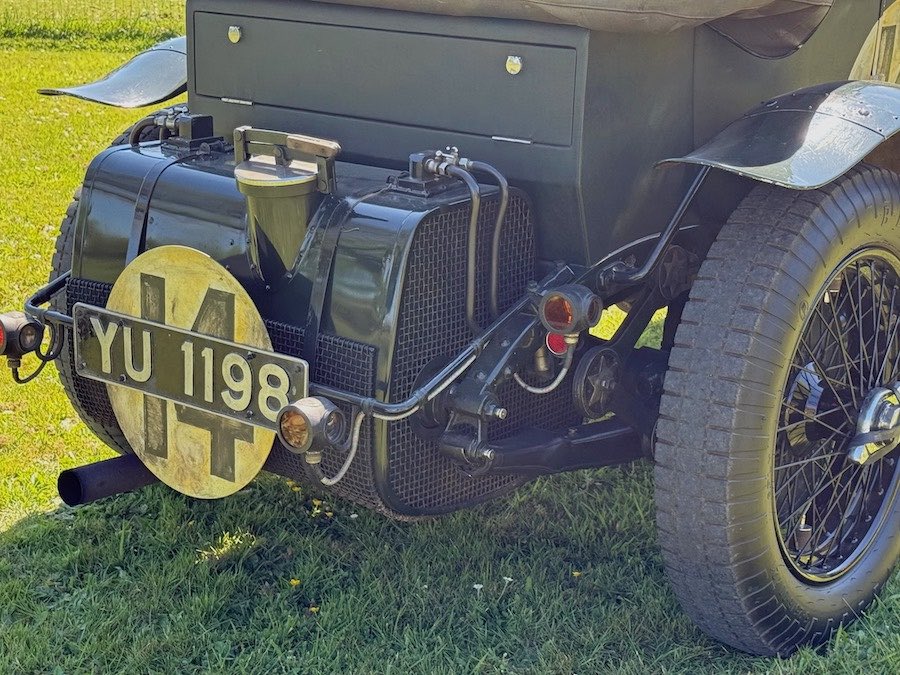
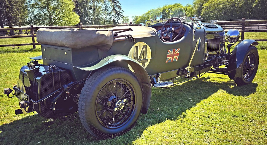
The “Le Mans”-style (large-capacity) fuel tank is visible and positioned at the rear of the chassis: it holds 25 imperial gallons of fuel (around 114 litres) for an average fuel consumption of approximately 15 MPG (19 litres per 100 km) when driving smoothly on flat terrain. Our car has a mileage counter in miles, but I use the GPS counter on my iPhone with audible alerts that sound every 30 miles (50 km). This procedure helps me keep track of the difference between the fuel level known at the start and my estimated consumption.
It is not advisable to fill up with fuel if you plan to drive short to medium distances: the fuel tank alone weighs around 110 pounds (50 kg), and if you add the 25 imperial gallons (114 litres) of fuel, the total weight causes a ‘nose-up’ effect, significantly lightening the front end of the vehicle.
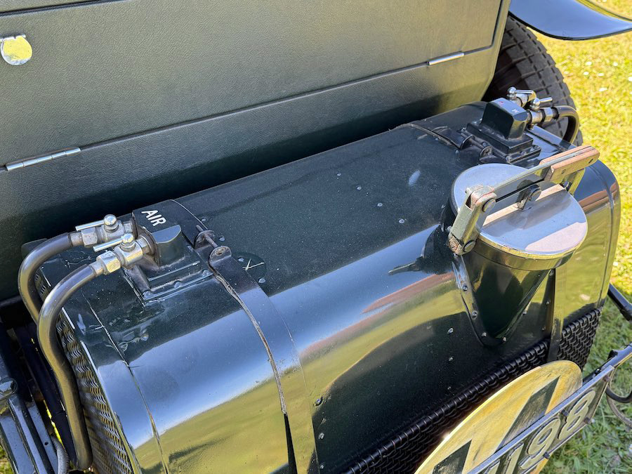
There are two vent valves on the left side of the tank and two valves on the right for opening and closing the main circuit and the reserve fuel system. When the engine starts to splutter, it is time to stop and open the reserve valve to gain about 35 extra miles (60 km), just long enough to find some fuel!
Once these first three checks (engine oil level, coolant level and fuel level) have been carried out, we can move on to actually starting the car.
START-UP PROCEDURE
Let’s go through all the components needed to get our Bentley 4½ Litre up and running. There are:
- a 12-volt battery,
- an alternator (replacing the original dynamo),
- two S.U. carburettors,
- two electric fuel pumps (one in use, the other as a backup in case of failure) to supply the fuel to the two S.U. carburettors,
- an ignition control and a throttle control on the steering wheel (we also have the main foot-operated throttle control),
- and two magnetos.
Battery and alternator
YU1198 is fitted with a 12-volt lead-acid battery, so called because it contains lead plates immersed in acid. This creates a chemical reaction that releases energy and provides us with voltage and current.
An alternator replaced the dynamo fitted to our car in 1928: alternators are more efficient thanks to a stronger magnetic field capable of providing a stable power supply both for immediate use and for recharging a battery – even at low revs. The dynamo only supplies current at a rotational speed of around 1,500 to 2,000 rpm, which is hardly compatible with the frequent stops of urban traffic.
This is only a personal opinion: some custodians of pre-war cars prefer the dynamo for its simplicity and ruggedness.
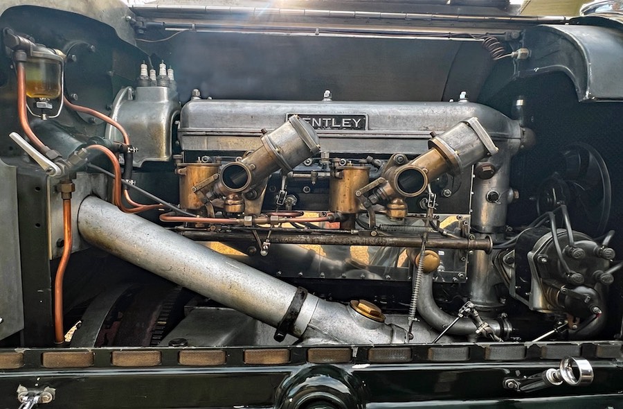
S.U. carburettors
This type of carburettor was produced in very large numbers throughout much of the twentieth century. The abbreviation S.U. stands for ‘Skinners Union’, referring to the partnership formed by brothers George, John and Carl Skinner in 1910.
This carburettor has fitted the majority of British cars (Bentley, Rolls Royce, Lagonda, Riley, MG, Jaguar, Triumph, Rover, etc. – S.U. carburettors remained on production cars through to 1994 in the Mini and the Maestro, by which time the company had become part of the Rover Group. During WW2, SU also manufactured the aero-carburettors and single point injection systems for many RAF aircraft. During the Battle of Britain in 1940, the Rolls-Royce Merlin engine in every Spitfire and Hurricane had an S.U. Carburettor.
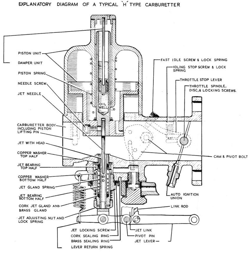
Unlike conventional carburettors, the S.U. carburettor uses a movable piston (with a conical needle) instead of a butterfly valve to regulate the air flow, which theoretically makes it operate more smoothly and efficiently.
When the engine is at idle, the piston is held down by a spring, which restricts the flow of air and fuel. As the throttle is opened, the piston rises, allowing more air and fuel to enter the engine.
The S.U. carburettor was not the original fitment on the Bentley 3-litre engine. Nevertheless, it was decided to test it on Frank Clement and John Duff’s car for their first entry in the 1923 Rudge-Withworth Cup (the name used prior to the “24 Hours of Le Mans”). In view of the car’s excellent performance during the race, W.O. and his team decided to fit all 1924 Red Label 3-litre Speed models with an SU G5 “sloper” carburettor.
An S.U. carburettor specialist explained to me that the “sloper” angle helped to reduce vibrations in the carburettor when driving on the rough, unpaved roads of the time. I haven’t been able to verify this theory.
Unsurprisingly, it was this same type of carburettor that would be fitted to the 4½-litre model from 1927 onwards.
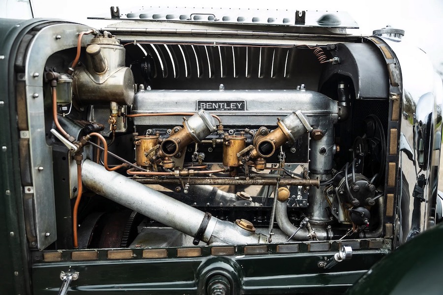
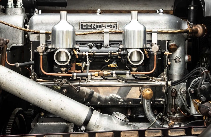
The twin S.U. G5 “slopers” were replaced in 1929 by vertically mounted S.U. HG5s, which had been tested for the first time at Le Mans in 1928. The main difference between the two models lay in the fact that the throttle butterflies were now part of the carburettor body and were no longer mounted in the intake manifold (as was the case with the ‘slopers’). The later carburettors were also fitted with flame dampers to protect the inside of the bonnet from backfires through the carburettors.
Many surviving vintage Bentleys were modified over decades: replacement carburettors were often fitted, some special or competition cars received non-original induction systems, and later restorations sometimes used H-series S.U.s (H4, HGV5, H6, H8, etc.) because they were easier to source and tune.
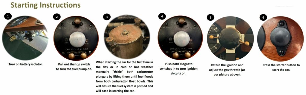
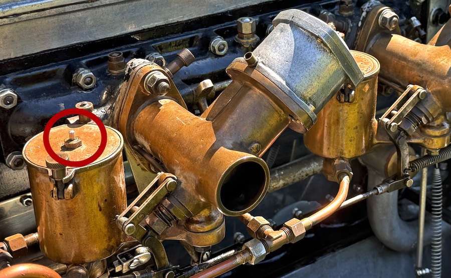
When starting the car for the first time in the day or in cold or hot weather, I manually “tickle” both carburettor plungers by lifting them until fuel floods from both carburettor float chambers. This will ensure the fuel system is primed and will ease in starting the car.
Electric Fuel pumps
YU1198 was originally fitted with an Autovac system, but following a discussion with my friend William Medcalf, director of Vintage Bentley, we decided to replace it with two electric fuel pumps (one is in use whilst the other serves as a backup in case the first one fails), with a view to ensuring both reliability and ease of maintenance.
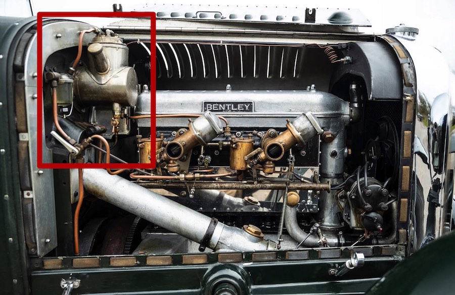
What is the origin of the Autovac and how does it work?
Well before the First World War, keen motoring enthusiast and businessman Joseph Higginson designed and manufactured the Autovac as a means of delivering fuel from rear mounted tanks without the need for pressurisation.
Used by some of the pioneering designers from the early days of motoring, Rolls Royce, Bentley, Lagonda, Lanchester among them, by the 1930s the Autovac was increasingly fitted by manufacturers who wanted to move the gravity-feed petrol tank from its traditional position above and behind the engine to a more convenient and safer location at the rear. The Skinner brothers’ SU fuel pump was not quite ready and the Autovac was favoured over the engine driven pump for its simplicity of construction and constant-level supply.
The Autovac system employs a small auxiliary tank usually mounted on the engine side of the dashboard, with its base above the carburettor float chamber. It is divided into two chambers — the inner or vacuum chamber being connected to the induction pipe and main petrol tank, and the lower or reserve chamber to the carburettor. Communication between the two is via the drop valve at the base of the inner chamber.
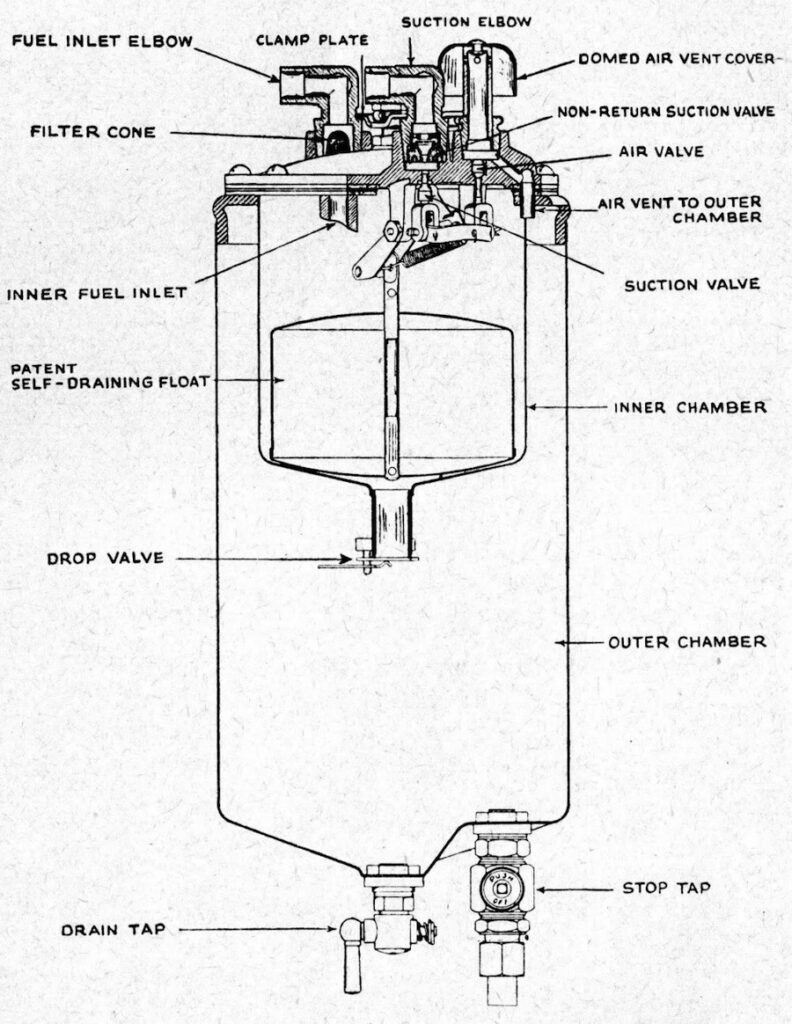
The engine suction creates a partial vacuum in the upper chamber, thus closing the drop valve and drawing up petrol from the main tank. As the fuel flows in, the float rises. When it reaches a certain height, two valves are operated — one cuts off the suction, the other admits air; this admission of air destroys the vacuum, releases the drop valve, and allows the petrol to flow into the outer chamber. The outer or reserve chamber is always open to the atmosphere through the air vent: thus the petrol in this chamber gravitates to the carburettor.
This sequence of operation continues until the reserve chamber is filled. The apparatus then ceases to function until the level is lowered, allowing the float to fall. As the float falls with the outflow of fuel from the inner chamber, the valve mechanism is again actuated and the operation of taking in fuel is repeated.
Most of the problems encountered with the Autovac relate to:
– blockages caused by foreign debris in the fuel,
– connections (in the suction section) coming loose and potentially leaking
– the two Autovac top gaskets ( cork/ composite) being very susceptible to decomposing with ethanol in the fuel, causing then lack of vacuum.
Some custodians of vintage Bentleys keep the Autovac, keen to preserve the car in its strictly original condition; others, like me, switch to electric fuel pumps, whilst others retain the Autovac for aesthetic reasons, but its function is disabled in favour of electric fuel pumps.
Electric starter
YU1198 rolled off the Bentley production line in April 1928, by which time hand cranks had been replaced by electric starters. This is fortunate, as by way of comparison, our 1911 Ford Model T Speedster originally required a hand crank, having no electric starter. To fire up the engine, we switch on the 6-volt battery before priming the fuel supply using a hand pump, which allows us to build up nominal pressure in the circuit leading to the carburettor.
We set the ignition to full retard with a touch of throttle on the steering wheel-mounted accelerator control (there is no foot accelerator on the Ford Model T), and… turn the crank! A mistake at any stage can cause a backfire, violently propelling the crank in the opposite direction of rotation. Wrist fractures were so common at the time that surgeons had coined a specific name for this injury: the ‘driver’s fracture’. But it could also lead to more tragic consequences.
The invention of the electric starter is closely linked to the American brand Cadillac and its founder, Henry Leland. In 1910, Leland learnt of the death of one of his friends, who had been killed by a kickback whilst starting a… Cadillac! Following this tragic accident, Leland asked his engineers to devise a starting system to replace the hand crank. Ultimately, the project was entrusted to Charles Kettering and his company, Delco. The electric starter was fitted to all Cadillacs from 1912 onwards. All American manufacturers adopted it in 1916, shortly before the majority of European manufacturers, including Bentley.
Today, when it comes to vehicles with internal combustion engines, the principle remains the same as in 1912: a powerful electrical impulse is sent to turn the engine until it fires. When you turn the key – or press “Start” – the starter motor receives a strong current from the battery and drives the flywheel at high speed. Once the engine has started, a relay automatically cuts off the power to prevent overheating.
The Smiths 4LSA starter motor was fitted as standard on all 3, 4½ and 6½ engines. The problem with the 4LSA lay in an original design flaw whereby the combination of a diameter that was too small and a significant length caused flexing, which could cause the shaft to bend over time – eventually leading to it breaking. The problem could be exacerbated by any unusual dynamics, such as a violent kickback caused by starting the engine at full advance.
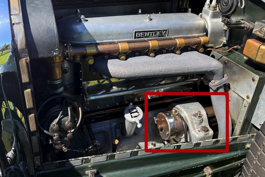
Many vehicles were ‘upgraded’ in the late 1920s with Bosch starters, which, thanks to their more robust design, proved to be ideal replacements for the Smiths models.
YU1198 is fitted with a Bosch starter motor, which was itself modified in the 1990s.
Ignition & throttle controls
The principle of ignition involves using a low-voltage current and converting it into a high-voltage current, which causes a spark to jump across the spark plug. This spark initiates the combustion of the air-fuel mixture, which is fed by the fuel pump to the carburettor and then compressed into a gaseous state within the ‘combustion chamber’ of each cylinder.
What is known as “ignition timing” refers to the spark from the spark plugs being triggered at a specific moment (generally before the piston reaches the top of its stroke) to ensure optimal combustion of the air-fuel mixture in the engine cylinder. The ignition timing must be adjusted according to the engine’s rotational speed (RPM). The faster the engine runs, the more the timing must be advanced.
It is necessarily set very low at start-up and when idling to ease the load on the crankshaft. Motorists of the time were accustomed to checking their engines’ performance ‘by ear’ and used the ignition timing adjustment to avoid changing gear whilst driving (which was awkward in the days of gearboxes without synchronisers – as is the case with YU1198). The ignition advance should be set to full (the “ADVANCED” position) on level ground and the advance should be reduced (towards the “RETARD” position) on a downhill gradient.
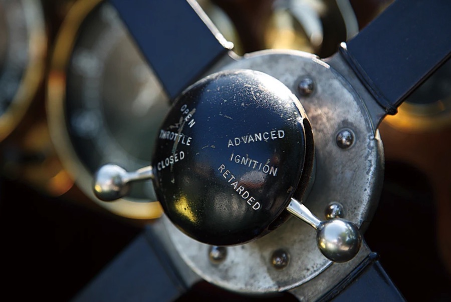
To start our Vintage Bentley, we therefore reduce the ignition advance at the steering wheel by setting the right-hand lever to a “RETARD” position (see photo) whilst applying a light touch of the accelerator: a good understanding of one’s car enables one to know the optimal position of this control for starting the engine.
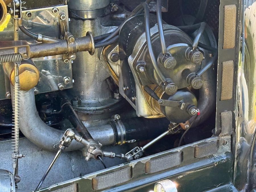
Magnetos
Like all 4½-litre models, YU1198 is fitted as standard with two magnetos. This is the M.L. ER4 model, derived from aeronautical applications by Morris & Lister (acquired in 1919 by Smiths under the name “M.L. Magneto Syndicate” before being sold to the equipment manufacturer Lucas in 1930).
The magneto is a self-contained generator of high voltage that provides ignition to an engine through spark plugs. A magnet – hence magneto – spins in close proximity to a coil of wire. As the magnet spins (or the magnet rotor is turned), it generates a strong magnetic force that is “held back” by a primary coil. The moment the contact points open, a rapid magnetic flow generates a high voltage in the secondary coil, which ignites the spark plug, thus firing the engine.
The two magnetos of the 4½ Litre are driven one at either end of the same cross shaft. They fire separate sets of sparking plugs and are synchronised to fire simultaneously.
The magnetos are of the stationary armature type, the magnets revolving and the windings being stationary.
This type of inštrument has several advantages. The high tension winding and condenser are stationary, there is no slip ring and pick-up, and the contact breaker not revolving, it is not subjećt to centrifugal force. The only revolving portion of the latter is a small cam. The distributor being of the jump spark type, there are no carbon brushes and no rubbing contačts in either high or low tension circuit, with the exception of a small brush on the axis of the distributor rotor where the rubbing speed is negligible.
The magnetos are flange mounted and are secured by three bolts on extensions of the aluminium cam casing. A damper is incorporated to nullify the fick of the magnetos on the cross shaft at low engine speeds.
Ordinarily the engine must always be run with both magnetos in operation as running one instruments switched off will damage it, and the plugs operated by that instrument may get sooted up. If however, one magneto should fail, the engine can run on the other until you arrive at destination.
The “4½ Litre Bentley Instruction book”, as published on February 1928, states that “Occasionally the magnetos should be tested to make certain that they are both firing regularly and that all sparking plugs are in oder. When running at about 25 mph on top speed with the engine pulling against a slight gradient, both magneto switches should be swicthed off alternate, when it will immediately be felt, by the irregularity of the engine, if either magneto or any plug is misfiring. Care must be taken that both magnetos are not switched off at the same moment, as immediately one or both are again switched on, an explosion in the silencer will be caused due to the unburnt gases which have passed into it and the silencer may be damaged”.
TIME FOR PRACTICE
Now that we’ve covered the theory, it’s time to put it into practice! Here are a few photos highlighting the key steps in starting the engine.